
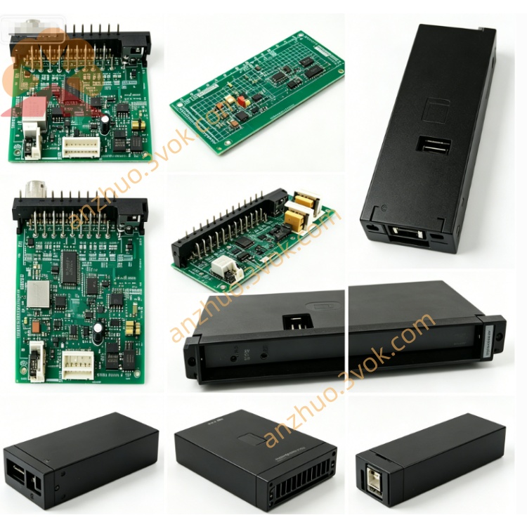
Reliance Electric 57406‑K high‑grade drive controller module
Description
Product Introduction
Model Interpretation
0‑57406‑K: Full AutoMax part number (leading 0 = standard control module).
57406: Product family = AutoMax Drive Controller Module.
‑K: Hardware revision K, featuring upgraded 16‑bit processor, enhanced fault diagnostics, improved noise immunity, and optimized thermal design. Fully backward compatible with earlier revisions (D/E/H).
Technical Parameters
Backplane Power: +5 VDC, ~650 mA.
Control Core: High‑performance 16‑bit microprocessor with advanced motion control firmware.
Isolation: 1500 VAC (field‑to‑logic).
Operating Temperature: 0 °C to +55 °C.
Humidity: 5%–95% non‑condensing.
Weight: ~1.6 kg (3.5 lb).
Front Panel: Fault code display, OK LED, 3‑position test switch, reset button.
Interface and Communication Configuration
Backplane Interface: Edge connector for AutoMax dedicated backplane bus (power + data exchange).
Drive Ports (Parallel):
TO POWER MODULE: Control/status signals to power modules.
GATE CONNECTOR BOX 1/2: Gate drive signals to power devices.
Configuration: Basic setup via front‑panel switches; programmable via AutoMax software for motion parameters and fault thresholds.
Core Functions
Executes closed‑loop speed, torque, and position control for AC/DC drives.
Generates and coordinates gate drive signals for precise power module switching.
Monitors drive health; logs and displays fault codes for rapid diagnosis.
Synchronizes multiple drives for coordinated motion (lines, webs, gantries).
Supports system diagnostics, test modes, and calibration via front‑panel controls.
Application Scenarios
Legacy AutoMax DCS/PLC maintenance in metallurgy, paper, power, and material handling.
Coordinated multi‑drive systems for rolling mills, conveyors, and web processing lines.
High‑precision motor control for actuators, spindles, and process equipment.
Retrofit/replacement of aging drive controllers in industrial automation modernization.
Operation and Maintenance Instructions
Installation: Power off the rack before insertion; align and seat firmly, tighten mounting screws.
ESD Protection: Use anti‑static wristband/mat; static damages sensitive circuits.
Wiring: Use shielded cables for drive/gate signals; separate from high‑voltage lines to avoid EMI.
Routine Maintenance: Quarterly inspection of cables/connectors; keep vents clean and dust‑free.
Troubleshooting: Read fault codes and check OK LED; verify switch settings and wiring before replacement.
Replacement: Replace entire module if internal fault; do not repair PCB.
Get a Quote