
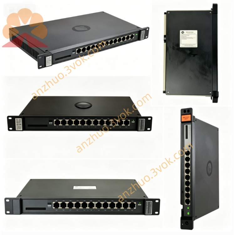
Reliance Electric 57404B edicated network communication module
Reliance Electric 57404B, also known as 0-57404-B, is a dedicated network communication module for AutoMax PLC and DCS systems. It adopts RS-232C based DCS-NET protocol to realize data transmission and interconnection between system racks, controllers and upper equipment. This product has been discontinued by the original manufacturer. Only refurbished, surplus and used products can be found on the market for maintenance and replacement of old automation systems.
Description
Product Introduction
Reliance Electric 57404B, also known as 0-57404-B, is a dedicated network communication module for AutoMax PLC and DCS systems. It adopts RS-232C based DCS-NET protocol to realize data transmission and interconnection between system racks, controllers and upper equipment. This product has been discontinued by the original manufacturer. Only refurbished, surplus and used products can be found on the market for maintenance and replacement of old automation systems.
Model Interpretation
The complete part number is 0-57404-B. The leading digit 0 represents standard functional modules of the AutoMax series. The code 57404 refers to the product category of DCS-NET communication module. The suffix B stands for hardware revision B, which is equipped with optimized circuit design, enhanced anti-interference and surge protection performance. This model number is used for product identification, ordering and inventory management.
Technical Parameters
This module applies the proprietary DCS-NET communication protocol based on RS-232C standard. The fixed communication baud rate is 845 kilobits per second. It supports multi-drop network structure and both peer-to-peer and master-slave working modes. The maximum effective transmission distance reaches 914 meters with standard cables. The node address can be set from 0 to 31 through the dial switches on the front panel. It obtains 5 VDC working power from the rack backplane. There is 1500 VAC isolation between external communication circuit and internal logic circuit. The operating temperature ranges from 0 degrees Celsius to 55 degrees Celsius, and it can work normally in the environment with relative humidity between 5 percent and 95 percent without condensation.
Interface and Communication Configuration
The module connects to the system backplane through edge connectors to acquire power and exchange internal data with the main controller. It is fitted with a 25-pin interface for external network connection, together with screw terminals for grounding connection. All data interaction between modules relies on the dedicated backplane bus of AutoMax system. It does not support additional external standard network ports. Basic network address setting is completed by physical dial switches on the panel.
Core Functions
It establishes stable DCS-NET communication links among multiple AutoMax racks and controllers to achieve real-time data sharing. It supports remote I/O control and data interaction between local equipment and host systems. It feeds back operating status and fault codes through onboard indicators to facilitate system diagnosis. It expands the operating capacity of distributed control systems and realizes synchronous operation of multiple sets of control units. It supports hot swapping under the matching system configuration.
Application Scenarios
It is mainly used as replacement spare parts for maintaining legacy AutoMax PLC and DCS equipment. It is widely applied in distributed control systems of metallurgy, papermaking, chemical industry and power industry. It suits automated production lines that require interconnection of multiple control racks and data interaction with upper monitoring systems. It is commonly used for daily maintenance and partial upgrading of old industrial automation projects.
Operation and Maintenance Instructions
Cut off the power supply of the entire rack before installation, removal and wiring. This module is sensitive to static electricity, so take complete anti-static protection measures during operation. Insert the module into the designated slot and ensure the connectors are fully connected, then fasten the fixing screws. Set the network node address correctly according to the on-site requirements, and use shielded cables for external communication wiring. Keep the module surface clean and ventilated during daily use. Regularly inspect cables and connectors for aging, looseness and corrosion. When communication failure occurs, check address settings and line integrity first. Replace the whole module directly if internal circuit faults cannot be solved.
Get a Quote