
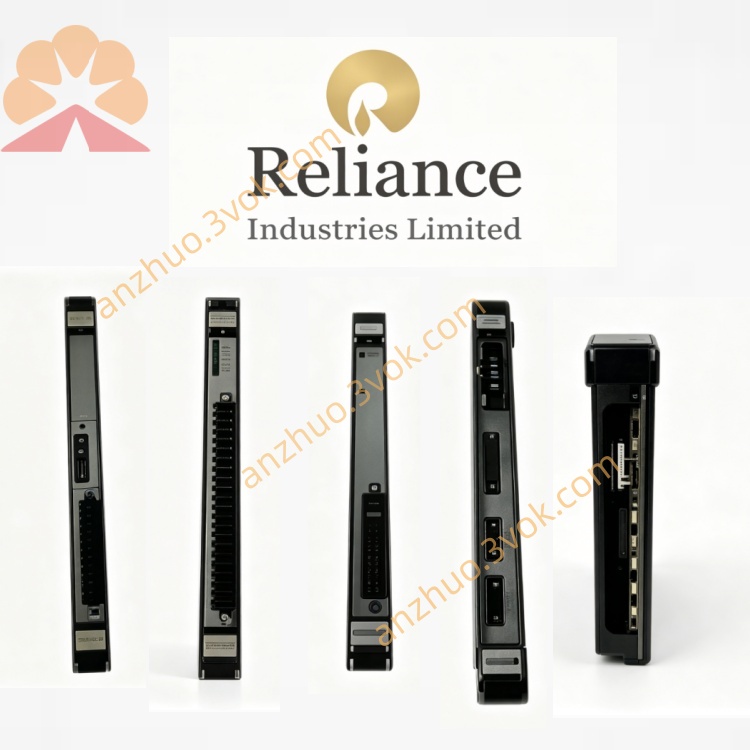
57403‑E (0‑57403‑E) 16‑point 115 VAC high‑power output module
Description
Product Introduction
Model Interpretation
57403‑E: Base model; E denotes hardware revision E (enhanced protection and components).
0‑57403‑E: Full AutoMax part number (leading 0 = standard I/O module).
57403: Product family = high‑power 115 VAC output module.
‑E: Revision with upgraded PCB, higher inrush tolerance, and improved surge suppression; backward compatible with earlier revisions.
Technical Parameters
Channels: 16 independent outputs (0–15).
Output Type: Solid‑state, 115 VAC (50/60 Hz).
Load Voltage: 70–132 VAC.
Rated Current: 2.0 A per channel; max total 32 A.
Inrush Current: High inrush capacity for capacitive/inductive loads.
Leakage Current: ≤2 mA (off‑state).
On‑State Resistance: <10 Ω.
Response Time: <12 ms.
Backplane Power: +5 VDC, ~600 mA.
Isolation: 2500 VAC field‑to‑logic; 1500 VAC channel‑to‑channel.
Protection: Overcurrent, short‑circuit, thermal shutdown, transient voltage suppression; self‑recovery after fault.
Operating Temperature: 0 °C to +60 °C.
Humidity: 5%–95% non‑condensing.
Weight: ~1.1 kg.
Interface and Communication Configuration
Backplane Interface: Edge connector for AutoMax dedicated backplane bus; provides power and data exchange with CPU.
Field Interface: Screw terminals (0–15) with four isolated common groups (C1–C4) (4 outputs per common).
Indicators: 16 channel status LEDs + power/fault LED on front panel.
Communication: No independent network ports; all I/O data via AutoMax backplane bus.
Core Functions
Converts 5 V logic signals from PLC into 115 VAC drive signals for high‑power field devices.
Drives motor starters, large solenoids, contactors, heaters, and high‑inrush loads.
Provides individual channel overcurrent/short‑circuit protection with automatic recovery.
Feeds back channel status to CPU for diagnostics and system monitoring.
Supports hot swapping in properly configured AutoMax systems.
Application Scenarios
Replacement/maintenance of legacy AutoMax PLC/DCS in heavy industry.
Process control in metallurgy, paper, chemical, and power sectors.
Driving 115 VAC high‑power devices in assembly lines, material handling, and machine tools.
Systems requiring high isolation and high inrush current capability.
Operation and Maintenance Instructions
Installation: Power off rack before insertion; align and seat firmly, tighten mounting screws.
Wiring: Connect loads to 0–15 and commons to C1–C4; use rated wire gauge, avoid over‑torque.
ESD Protection: Use anti‑static wristband/mat when handling; static may damage circuits.
Routine Maintenance: Quarterly inspection of terminals for looseness/corrosion; keep clean and dust‑free.
Troubleshooting: Check channel LEDs; verify load voltage/wiring before module replacement.
Replacement: Replace entire module if internal fault; do not repair PCB.
Get a Quote