
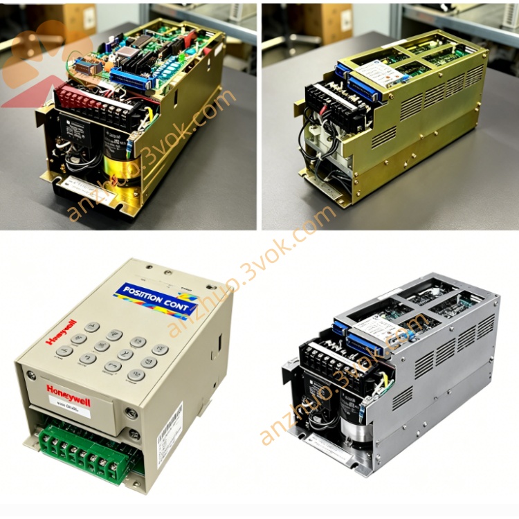
Yaskawa CACR-SR15SZ1SS-Y125
CACR-SR15SZ1SS-Y125 is a 1.5 kW AC servo drive belonging to Yaskawa legacy VS-800 CACR-SR series. It operates with three-phase 200 to 230 VAC power supply and adopts special hardware structure matched with serial encoder interface. This unit is loaded with standard base firmware and Y125 dedicated OEM parameters, which are pre-configured for specific machine tools and automation equipment. This model has been officially discontinued by the manufacturer. Currently, only fully tested second-hand and refurbished units are available for on-site maintenance, equipment repair and spare part replacement.
Description
1.1 Product Overview
CACR-SR15SZ1SS-Y125 is a 1.5 kW AC servo drive belonging to Yaskawa legacy VS-800 CACR-SR series. It operates with three-phase 200 to 230 VAC power supply and adopts special hardware structure matched with serial encoder interface. This unit is loaded with standard base firmware and Y125 dedicated OEM parameters, which are pre-configured for specific machine tools and automation equipment. This model has been officially discontinued by the manufacturer. Currently, only fully tested second-hand and refurbished units are available for on-site maintenance, equipment repair and spare part replacement.
1.2 Model Number Explanation
CACR represents AC servo drive also named SERVOPACK. SR stands for speed and position control type of the VS-800 product platform. The number 15 refers to the rated power of 1.5 kW. The letter S means the drive is fully compatible with Yaskawa S-series servo motors. The letter Z indicates special customized hardware including dedicated input, output and feedback circuits. Digit 1 signifies single-phase 200 VAC power supply for the internal control circuit. The second letter S represents serial encoder interface designed for S-series motors. The last letter S stands for standard base firmware. The suffix Y125 refers to a complete set of OEM customized parameters preset for designated industrial equipment.
1.3 Applicable Equipment
This servo drive is specially designed for Yaskawa 200 VAC, 1.5 kW class S-series servo motors equipped with serial encoders. It cannot work normally with motors using incremental encoders or non-S-series motors unless corresponding hardware and firmware modifications are completed.
2. Technical Specifications
2.1 Electrical Parameters
The main power input is three-phase 200 to 230 VAC with voltage tolerance from minus 15 percent to plus 10 percent, and the applicable frequency ranges from 50 Hz to 60 Hz. The control circuit is powered by single-phase 200 to 230 VAC with the same voltage tolerance and frequency range. The rated output power is 1.5 kW. The continuous output current is 9.9 A, and the peak output current reaches 28 A which can be sustained for up to 30 seconds. The output frequency range is 0 Hz to 400 Hz. The encoder interface follows Yaskawa exclusive serial communication protocol for S-series motors.
2.2 Environmental Requirements
The allowable operating ambient temperature is from 0 degrees Celsius to 55 degrees Celsius. The storage temperature ranges from minus 20 degrees Celsius to 85 degrees Celsius. The relative working humidity shall not exceed 90 percent, and condensation is strictly prohibited in all working states. For vibration resistance, the unit can withstand 0.5 g vibration within 10 Hz to 60 Hz and 0.2 g vibration within 60 Hz to 200 Hz. The rated working altitude is within 1000 meters above sea level. When the altitude exceeds 1000 meters, the output power needs to be reduced by 1 percent for every additional 100 meters.
2.3 Mechanical Parameters
The drive adopts vertical panel mounting method. The overall dimensions are 380 millimeters in height, 150 millimeters in width and 200 millimeters in depth. The total weight is about 5.5 kilograms. The internal cooling mode is forced air cooling supported by a built-in fan.
3. Main Features
The serial encoder interface delivers stronger anti-interference capability and supports longer connection distance compared with traditional incremental encoders, and the maximum cable length can reach 50 meters. The built-in Y125 OEM parameters are optimized for specific production equipment, which greatly reduces the workload of on-site parameter tuning and commissioning. This drive supports multiple control modes including analog speed control and torque control via ±10 VDC signal, as well as pulse direction type position control. It is equipped with RS-232C and RS-485 communication interfaces that support Modbus RTU protocol to realize remote parameter setting and data transmission.
Complete protection functions are integrated inside the unit, covering overcurrent, overvoltage, undervoltage, over temperature, encoder fault and overload protection. It can withstand 150 percent overload load for 60 seconds in normal operation. A seven-segment digital display is configured on the panel to show real-time operating status and alarm information for convenient daily inspection and fault diagnosis.
4. Installation and Wiring Instructions
4.1 Mounting Requirements
Install the servo drive vertically on a firm panel with good shock resistance. Reserve at least 50 millimeters of space above and below the unit to ensure smooth air circulation for heat dissipation. Do not install the device in places exposed to direct sunlight, oil mist, heavy dust or corrosive gas. Keep the mounting surface flat to avoid additional mechanical stress on the drive.
4.2 Main Circuit Wiring
Terminals R, S and T are connected to the three-phase main power input. Terminals L1 and L2 are connected to the single-phase control power supply. Terminals U, V and W are connected to the corresponding terminals of the servo motor. Terminals P and B are reserved for external regenerative resistor connection according to actual working conditions. Terminal PE must be reliably connected to protective ground for operational safety.
4.3 Encoder Wiring
Connect the serial encoder cable to the CN2 9-pin D-sub interface. Use shielded twisted-pair cables for wiring, and only ground the shielding layer at the drive end to prevent ground loop interference. Keep the encoder cable within 50 meters to guarantee signal stability. Check the pin definition and fasten the connector firmly after wiring.
4.4 Control Signal Wiring
The CN1 50-pin interface is used for all control signal connections. The input signals include servo enable signal, forward and reverse operation signal, alarm reset signal, emergency stop signal and position command pulse. The output signals contain servo ready signal, alarm feedback signal, brake release signal and speed arrival signal. The analog signal part provides ±10 VDC speed and torque command input and corresponding speed monitoring output.
5. Parameter Settings
5.1 Basic Operating Parameters
Parameter Pn000 is used to select control mode, with 0 for speed control mode, 1 for position control mode and 2 for torque control mode. Parameter Pn100 sets the speed loop gain with Y125 default value. Parameter Pn101 adjusts the integral time constant of speed loop, and the default setting is 20 milliseconds. Parameter Pn200 corresponds to position loop gain. Parameter Pn300 sets the overload protection threshold with default value of 150 percent. All above parameters are preset according to Y125 application requirements before delivery.
5.2 Communication Parameters
Parameter Pn500 sets the communication address of the drive, ranging from 1 to 31 with default address 1. Parameter Pn501 configures communication baud rate, and the factory default is 9600 bps. Parameter Pn502 defines data format as 8 data bits, no parity bit and 1 stop bit.
6. Alarm Information and Troubleshooting
The display content A.00 means the drive runs normally without any fault. When A.31 appears, it indicates overcurrent fault, which is usually caused by motor short circuit, wiring failure or excessively high control gain. Users need to check the circuit and motor status, and properly reduce the gain parameters. The alarm code A.40 stands for over temperature fault, resulting from fan damage, poor ventilation or long-term overload operation. Clean the fan and air ducts, improve the heat dissipation environment and check the actual load.
Code A.51 represents encoder fault, which may be caused by broken cables, damaged encoder components or strong electromagnetic interference. Inspect the integrity of encoder cables and connectors, and check the shielding and grounding conditions. Code A.80 is undervoltage alarm, mostly due to abnormal input power supply or loose wiring terminals. Verify the input voltage and re-tighten all power connection terminals.
7. Daily Maintenance
Check the content of digital display, the running state of cooling fan and whether there is abnormal noise or vibration during daily operation. Conduct monthly maintenance to clean the air inlet and filter, tighten all terminal screws and inspect all cables for aging and damage. Complete annual maintenance work including replacing aging cooling fan, checking electrolytic capacitors for bulging and liquid leakage, and reconfirming the reliability of all electrical connections.
8. Compatibility Description
This model shares the same hardware structure with CACR-SR15SZ1SS series products. The core difference lies in internal firmware and parameter groups. CACR-SR15SZ1SS-Y125 is equipped with exclusive Y125 parameters, which cannot be directly interchanged with other parameter versions without parameter reconfiguration. When replacing the drive on site, confirm the matched motor type is serial encoder S-series motor, and keep the Y125 parameter group unchanged to ensure consistent equipment performance.
9. Disclaimer
This content is an excerpt from the official user manual of Yaskawa CACR-SR series servo drives. For complete safety operation specifications, detailed wiring diagrams and full parameter list, please refer to the original official manual. The manufacturer shall not be responsible for equipment damage or safety accidents caused by improper installation, unauthorized modification and non-standard operation.
Get a Quote