
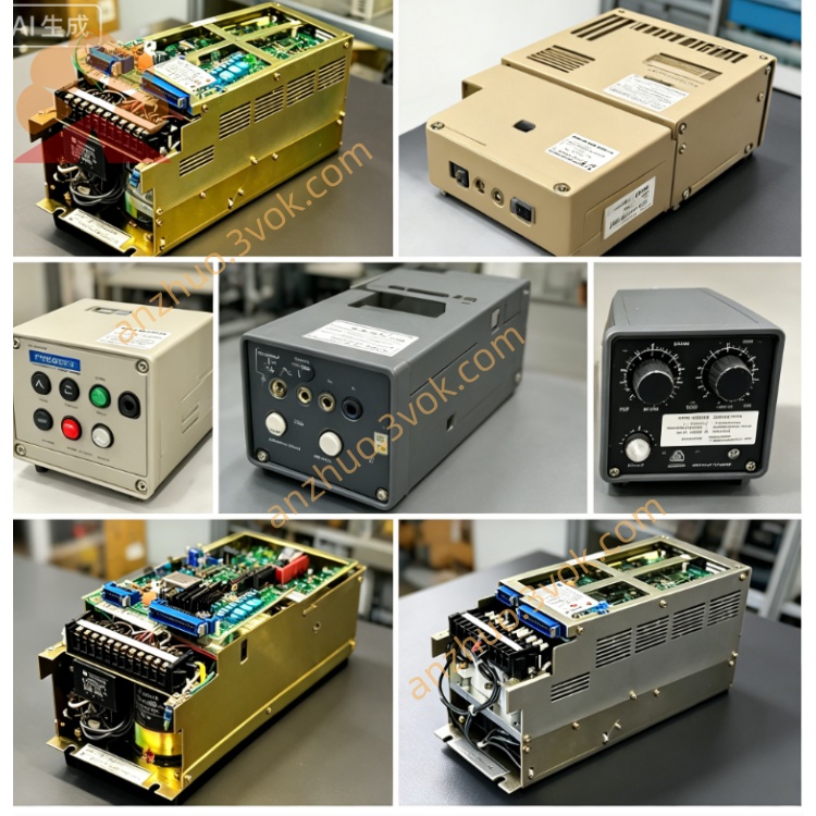
YASKAWA CACR-SR02AC1ER-Y3
Model: CACR-SR02AC1ER-Y3
Series: CACR-SR SERVOPACK
Rated Power: 200W
Rated Voltage: 200VAC
Reference Manual: KG22E (CACR-SR Series English Version)
Description
1. SAFETY PRECAUTIONS
High voltage remains inside the unit after power is cut off. Disconnect the power supply and wait at least 5 minutes before conducting wiring, inspection or maintenance. Always connect the PE terminal to protective earth to prevent electric shock. Do not run the drive beyond its rated torque and duty cycle to avoid overload damage. Unauthorized modification of the device is prohibited, as it will void the warranty and may cause fire or personal injury. An external emergency stop circuit shall be installed to cut off power immediately under abnormal conditions.
2. MODEL CODE EXPLANATION
CACR refers to AC Servo Drive. SR stands for speed and position control type SERVOPACK. The digit 02 represents a rated power of 200W. Letter A means the drive is compatible with R-series servo motors. Letter C indicates the product design revision. Digit 1 denotes 200VAC power input and analog ±10V speed command input. Letter E means the unit matches a 1500 ppr incremental encoder. Letter R stands for rack mounting type. Y3 is a customized version, which shares the same wiring, parameters and basic functions with standard models of the same series.
3. TECHNICAL SPECIFICATIONS
3.1 General Specifications
The drive accepts single-phase 200V to 230V AC input with a frequency of 50Hz to 60Hz. The three-phase output ranges from 0V to 230V AC, and the rated output current is 1.5A. The main control mode is analog speed control via ±10V command signal. The matched encoder is a 1500 ppr incremental type. Built-in protection functions include overcurrent, overvoltage, undervoltage, overheat and encoder fault protection. The operating ambient temperature is from 0°C to 45°C, and the storage temperature ranges from -20°C to 60°C. The relative ambient humidity shall not exceed 90 percent, and condensation is not allowed.
3.2 Factory Default Parameters
The default position loop gain is 40. The default speed loop gain is 200. The speed loop integral time is set to 20 milliseconds. The default encoder resolution is 1500 ppr. The full range of ±10V analog input corresponds to the motor rated speed.
4. INSTALLATION AND WIRING
4.1 Installation Requirements
Mount the drive vertically with the heat sink facing down. Keep a clearance of no less than 100 millimeters at the top and bottom, and no less than 50 millimeters on both sides. Ensure unobstructed air flow around the device. Keep the unit away from direct sunlight, dust and oil mist during installation and operation.
4.2 Main Circuit Wiring
Terminals R and S are for AC power input. Terminals U, V and W connect to the three-phase servo motor. The PE terminal must be firmly connected to protective earth. The RB terminal is reserved for connecting an external regenerative resistor according to actual operating demands.
4.3 Control Circuit Wiring
Connector 2CN is used for control input and output signals. SG is the signal ground terminal. VREF receives the ±10V analog speed command signal. FWD and REV are optocoupler driven terminals for forward and reverse operation. E-STOP serves as the emergency stop terminal. ALM is the alarm signal output terminal with relay contacts.
Connector 5CN is specially designed for encoder connection. Terminals A, /A, B and /B transmit encoder phase signals. +5V and GND supply operating power for the encoder.
5. OPERATION AND DISPLAY
The unit is fitted with a 7-segment LED display. The digit 0 will show on the display when power is connected normally. The real-time motor speed will be displayed during regular operation. The corresponding fault code will appear once a malfunction occurs.
Complete all wiring for power, motor and encoder and check connections carefully before use. You may use factory default parameters or adjust settings as required. Input analog speed command signals to start the motor, and switch running direction via forward or reverse signals. Keep observing the LED display to monitor operating status and fault information.
6. FAULT CODES AND TROUBLESHOOTING
Code 1 indicates an overcurrent fault. This fault is generally caused by circuit short circuit, motor overload or incorrect wiring. Check the connection of U, V and W terminals and reduce the load appropriately.
Code 2 refers to an overvoltage fault, which is mainly triggered by excessive regenerative energy or input voltage surge. Connect an external regenerative resistor and check the stability of the power supply.
Code 3 stands for an undervoltage fault, resulting from insufficient input voltage or loose terminals. Inspect the power supply and retighten all wiring terminals.
Code A represents an encoder fault. Check for broken cables or loose connectors on the encoder line, then reconnect cables or replace the faulty encoder.
Code F means an overheat fault. Poor ventilation, damaged cooling fan or long-term overload will lead to this alarm. Clean the heat sink, inspect the cooling fan and reduce the operating load.
Code B and Code C are internal system faults of the drive. If these codes appear, the control board may be damaged and the whole drive needs to be replaced.
7. ROUTINE MAINTENANCE
Check the LED status, abnormal noise and surface temperature of the drive every day. Clean the heat sink and cooling fan, and check the tightness of all wiring terminals every month. Inspect the working condition of the cooling fan and test the performance of internal electrolytic capacitors every year. The service life of internal electrolytic capacitors is about 5 years, and the cooling fan can work stably for around 3 years. Replace aging components in time to guarantee reliable operation.
Get a Quote