
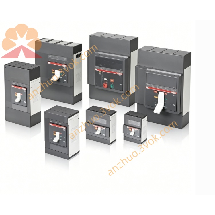
ABB 57310001-LM (DSCS131) high‑performance I/O communication module
Description
Product Introduction
Model Interpretation
57310001‑LM: ABB material number for ordering and traceability.
DSCS131: Product series (communication board for AC 400/MasterPiece).
57310001: Base part number; ‑LM: hardware version/confguration variant.
Technical Parameters
Module Type: Dual‑channel isolated communication board.
Power Supply: 24 V DC (via rack backplane, 19.2–30 V DC).
Current Consumption: Approx. 100 mA.
Operating Temperature: 0 °C to +60 °C.
Storage Temperature: ‑40 °C to +85 °C.
Isolation Voltage: ≥500 VRMS (bus‑to‑backplane).
Protection Class: IP20.
Dimensions: 228.6 × 19.8 × 321.3 mm.
Weight: Approx. 0.46 kg.
Certifications: CE, UL, CSA, RoHS.
Interface and Communication Configuration
Bus Interface: MasterBus 300 / AF100 proprietary bus (controller side).
I/O Interface: Dual isolated channels for remote I/O racks.
Data Rate: Up to 1 Mbps (bus).
LED Indicators: Power, RUN, FAULT, and communication status for diagnostics.
Backplane Connection: AC 400 series subrack, plug‑in design.
Cabling: Shielded twisted pair recommended; separate from power cables for EMC.
Core Functions
Bus Extension: Connects central controller to distributed I/O racks, extending control reach.
Real‑Time Data Exchange: High‑speed, low‑latency communication for time‑critical process control.
Electrical Isolation: 500 VRMS isolation reduces ground loops and EMI in harsh environments.
Redundancy Support: Enables redundant communication paths for high‑availability systems.
Diagnostics & Monitoring: Onboard LEDs and controller‑based monitoring for quick fault localization.
Hot‑Swap: Supports replacement during system operation in compatible redundant racks.
Application Scenarios
System Compatibility: ABB AC 400, MasterPiece 200/200/1, Symphony Harmony, INFI 90 DCS.
Industries: Power generation, oil and gas, chemical, pulp and paper, metallurgy, water treatment.
Typical Uses: Connecting remote I/O racks, PLCs, and third‑party devices to AC 400 controllers; legacy system maintenance.
Operation and Maintenance Instructions
Installation: Insert into designated slot of AC 400 subrack; ensure proper grounding and cooling clearance.
Wiring: Use shielded twisted pair for bus lines; isolate from AC power cables to avoid interference.
Configuration: Set bus address, data rate, and redundancy mode via system engineering tools.
Maintenance: Inspect connections and LEDs quarterly; clean dust with dry cloth; update firmware during scheduled downtime.
Replacement: Hot‑swap in redundant systems; power off non‑redundant racks before removal.
Troubleshooting: Check LED status; verify cabling and termination; use controller diagnostics for fault isolation.
Get a Quote