
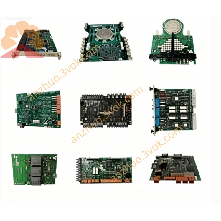
ABB 1SAP220000R0001 (DC505‑FBP) 8DI/8DC digital I/O interface module
1SAP220000R0001 is DC505-FBP, a digital input and output module belonging to ABB S500 distributed I/O system. It adopts FBP fieldbus plug design, equipped with 8 digital inputs and 8 digital outputs working at 24 V DC. This module integrates I/O collection and fieldbus communication functions, and matches AC500 series PLC to realize signal transmission and device control in industrial automation.
Description
Product Introduction
1SAP220000R0001 is DC505-FBP, a digital input and output module belonging to ABB S500 distributed I/O system. It adopts FBP fieldbus plug design, equipped with 8 digital inputs and 8 digital outputs working at 24 V DC. This module integrates I/O collection and fieldbus communication functions, and matches AC500 series PLC to realize signal transmission and device control in industrial automation.
Model Explanation
1SAP220000R0001 is the official ABB part number. DC505-FBP is the product model, DC stands for digital input and output module, 505 represents the model code of S500 series, and FBP refers to Fieldbus Plug interface. 220000 is the platform code for S500 FBP I/O modules, and R0001 means the original hardware revision. This module needs to be used together with corresponding FBP terminal units, and cannot work independently.
Technical Parameters
The module is powered by 24 V DC from the backplane with power consumption less than 1 watt. It has 8 channels of 24 V DC digital inputs and 8 channels of 24 V DC digital outputs, and each output channel supports rated current of 0.5 ampere. It supports Modbus RTU and CANopen fieldbus protocols. The protection class is IP20. The operating temperature ranges from minus 20 degrees Celsius to 60 degrees Celsius, and the storage temperature ranges from minus 40 degrees Celsius to 70 degrees Celsius. The applicable relative humidity is 0 percent to 95 percent without condensation. The overall weight is about 0.2 kilograms. It is installed on standard DIN rail. The product complies with CE, UL, CSA and RoHS standards. It is fully compatible with AC500 V2, V3, AC500-eCo and AC500-S PLCs as well as S500 supporting terminal units.
Interface and Communication Configuration
It is equipped with FBP backplane interface to connect S500 terminal units and AC500 system bus, featuring plug and play performance. Field devices are connected through built-in screw terminals. It communicates with external devices via Modbus RTU and CANopen protocols. The module supports hot swap function. Multiple LED indicators are arranged on the panel to display power status, bus operating status and on-off state of each input and output channel. No extra network configuration is required for basic connection.
Core Functions
It collects switching signals from on-site sensors through digital input channels. It drives peripheral equipment such as relays, valves and contactors through digital output channels. It realizes data interaction between AC500 PLC and external slave devices via fieldbus. It provides signal isolation and surge protection to ensure stable operation of signals. It expands the remote I/O capacity of the control system and realizes distributed control layout.
Application Scenarios
It is applicable to automation projects built with ABB AC500 PLC and S500 I/O system. It is widely used in production lines, packaging equipment and material handling machinery in factory automation. It can be used for pump and valve control as well as signal monitoring in process automation. It is also suitable for assembly equipment and mechanical transformation projects that require 24 V DC digital signal acquisition and control.
Usage and Maintenance Instructions
Install the module on standard DIN rail inside the control cabinet and keep the surrounding area well ventilated, dry and away from dust and condensed water. Connect 24 V DC power supply with correct polarity. Insert the module into the matched FBP terminal unit and lock it firmly. Connect field cables to screw terminals and tighten screws with proper torque. Complete fieldbus parameter configuration through AC500 programming software according to actual demands. Observe LED indicators regularly to judge operating status. Check terminal tightness and surface dust periodically and clean up in time. When abnormal conditions occur, firstly inspect power supply, bus connection and indicator status, and replace the module if it is confirmed damaged.
Get a Quote