
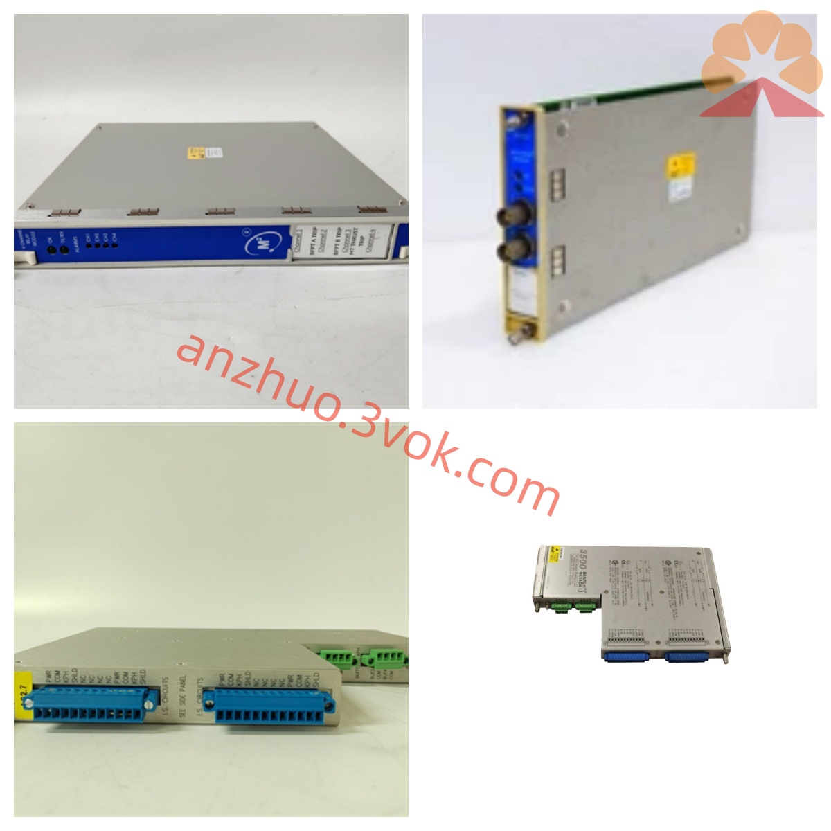
Bentley 3300/16-03-01-00-00-00-02 Product Description
Description
Bentley 3300/16-03-01-00-00-00-02 Product Description
I. Product Introduction
The Bentley 3300/16-03-01-00-00-00-02 is a dual-channel XY/GAP vibration and shaft clearance monitoring module of the Bentley Nevada 3300 series, developed specifically for online condition monitoring and safety protection of large industrial rotating machinery. This module can simultaneously complete continuous monitoring of two paths of vibration and shaft clearance, effectively identifying typical faults such as rotor imbalance, misalignment of the shaft system, bearing wear, and deviation of the shaft position. The equipment integrates functions such as data acquisition, local numerical display, graded alarm, relay output, hardware self-diagnosis, and remote communication, adopts a standard modular structure, is compatible with the 3300 series dedicated chassis, has strong anti-electromagnetic interference capability, operates stably and reliably, and is widely used in core power units of industries such as power, petrochemicals, metallurgy, and water treatment, providing solid support for equipment fault early warning, status control, and safety interlock.
II. Basic Information
This product is manufactured by Bentley Nevada and belongs to the 3300 industrial condition monitoring series. The model is 3300/16-03-01-00-00-00-02. The equipment type is a dual-channel radial vibration and shaft clearance integrated monitor. Its core functions include dual-channel vibration amplitude measurement, gap voltage collection, calculation of the average position of the shaft, output of over-limit alarms, self-diagnosis of faults, and remote parameter management. The product is compatible with 3300 XL, 7200 series eddy current probes and their accompanying preamplifiers. The standard probe sensitivity is 200mV/mil, and it can be matched with mainstream sensing accessories in industrial sites. The entire machine is installed in a 19-inch standard rack, and can be directly assembled in the same series of monitoring chassis. The product complies with CE electromagnetic compatibility standards and can operate continuously in industrial sites with high dust content, complex electromagnetic environments, and significant temperature and humidity variations.
III. Functions and Positioning
The module is equipped with two completely isolated independent measurement channels. The signals between the channels do not interfere with each other. It can simultaneously monitor the radial vibration in the X and Y directions of a single rotating equipment, or separately monitor the operating parameters of two different equipment. The two sets of data are independently calculated, and the alarm and output logic are independent. While detecting the vibration amplitude, the equipment continuously collects the gap voltage between the shaft and the bearing and converts it into the average operating position of the shaft, achieving dual monitoring of vibration and shaft system position, and comprehensively reflecting the operating conditions of the rotor and the bearing.
The equipment is equipped with a warning and danger two-level alarm system. The alarm threshold and alarm delay of each channel can be flexibly set through the local panel or the upper-level monitoring software. When the monitoring parameters exceed the preset limit, the corresponding status indicator light on the panel lights up simultaneously, and the relay output switch quantity signal is generated, which can be connected to the on-site sound and light alarm device and the unit interlock system to achieve graded safety protection. The module supports single-channel or dual-channel bypass functions. During sensor calibration, line maintenance, and equipment maintenance, the alarm output can be temporarily shielded without affecting the normal operation of other functions of the system, ensuring the continuous operation of the entire monitoring system.
The module is equipped with a complete fault self-diagnosis circuit, which can detect sensor breakage, line short circuit, abnormal input signals, and hardware faults of the module itself. When an abnormal state occurs, the operation indicator light goes out, and it promptly reminds the maintenance personnel to carry out fault troubleshooting. The module is equipped with a sensor signal buffer output interface, which can be connected to detection equipment such as oscilloscopes and data acquisition instruments for on-site signal verification, equipment debugging, and in-depth analysis of faults. This model has no analog output, no industry-specific certification, and no built-in safety barrier. It is a standard relay output type. The end code corresponds to the exclusive hardware version and supporting configuration, meeting the requirements for routine industrial monitoring and interlock use.
IV. Core Performance Parameters
The input signal of the equipment is the gap voltage output by the eddy current preamplifier. The reference voltage is -24V DC. The two input channels adopt high input impedance design to effectively avoid signal attenuation during transmission. The frequency response is divided into two working modes. The high-frequency mode has a frequency range of 4Hz to 4000Hz, suitable for various high-speed rotating mechanical equipment; the low-frequency mode has a frequency range of 1Hz to 600Hz, suitable for low-speed units. The low-frequency mode is not recommended for equipment with an acceleration rate exceeding 1000rpm/s, to prevent data distortion in monitoring.
The full-scale range of vibration measurement is 0 to 250 micrometers peak-to-peak, with a measurement accuracy of ±1% of the full scale. The gap voltage measurement range is -2V to -22V DC, with a voltage measurement accuracy of ±0.1V. The display resolution of the equipment panel is 0.1 micrometers and 0.1V DC, with clear and precise readings. The power supply can be -18V DC or -24V DC. The module has an independent current-limiting protection circuit built-in, and the maximum power consumption of the entire machine does not exceed 5W. The power supply voltage fluctuates within ±10% of the rated value, and the equipment can maintain stable operation.
The alarm system is divided into two levels: warning and danger. Each channel is independently configured. The rated parameters of the relay contacts are 24V DC, 1A, supporting both normally open and normally closed modes. The alarm delay time can be programmed within 0 to 10 seconds, effectively filtering instantaneous interference signals and reducing the probability of false alarms.
In terms of environmental adaptability, the normal operating temperature range of the equipment is -40℃ to +70℃, the storage temperature range is -52℃ to +105℃, the applicable relative humidity is 5% to 95%, and the operating environment requires no condensation. The front of the equipment is equipped with an LED digital display screen, allowing for free switching to view the vibration values and gap voltages of the two channels. It is also equipped with independent status indicator lights for operation, bypass, warning, and danger. The integrated RS-485 communication interface can be connected to the system host to complete remote parameter configuration, real-time data reading, and alarm status monitoring.
V. Model Code Explanation
3300 is the code for the entire monitoring product series of the Leebert 3300. 16 represents the XY/GAP dual-channel vibration and shaft gap monitor. 03 represents the full-scale range of vibration measurement is 0 to 250 micrometers peak-to-peak. 01 represents the compatibility with the standard 3300/7200 probe system, with a standard sensitivity of 200mV/mil. 00 represents no analog output configuration. The first 00 represents no additional industry-specific certification. The second 00 represents no built-in safety barrier configuration. The last 02 represents the exclusive hardware version and supporting function configuration.
VI. Applicable Equipment Domains
The power industry is mainly applied to steam turbine generator sets, boiler induced draft fans, supply fans, large circulating water pumps, etc. of power station core auxiliary equipment. The petrochemical industry is suitable for centrifugal compressors, screw compressors, high-temperature process pumps, and complete sets of refining and chemical units, etc. of continuous-running key rotating equipment. The metallurgical industry can be used for high-temperature blast fans, rolling mill units, dust removal fans, etc. of equipment. It is also applicable to large-scale circulating water pumps in water supply systems and various medium-high-speed rotating machinery in industrial and mining enterprises, providing reliable data and control support for equipment condition assessment, early fault warning, and safety interlock shutdown.
VII. Installation and Maintenance Key Points The equipment is installed in a 19-inch standard rack. During assembly, sufficient spacing is reserved between the modules to ensure ventilation and heat dissipation, and to prevent temperature accumulation from affecting the equipment's operational performance. During wiring operations, the A and B signal channels, positive and negative power terminals, relay output terminals, and communication terminals are strictly distinguished. Wiring is done in accordance with the marking specifications to avoid incorrect connections or reverse connections, which could cause equipment damage or abnormal monitoring data. It is recommended to perform channel accuracy calibration using the original factory standard probes and calibration tools every six months. After calibration, the parameters should be locked to prevent unauthorized personnel from modifying the settings at will.
During daily operation and maintenance, keep the equipment panel and the interior of the cabinet clean. Prevent dust and oil from entering the modules. Regularly inspect all wiring terminals and promptly tighten loose lines to avoid signal jumps caused by poor contact. When the equipment triggers fault alerts or abnormal alarms, follow the sequence of first checking the sensors and connection lines, and then testing the monitoring module itself to gradually locate the problem. When using the low-frequency working mode, it is prohibited from being applied to rapid start-stop units to prevent deviations in monitoring data. The communication lines should be kept away from strong power cables to reduce the impact of electromagnetic interference on signal transmission. This model is a standard hardware version. During use, do not disassemble or modify the hardware structure privately.
Get a Quote