
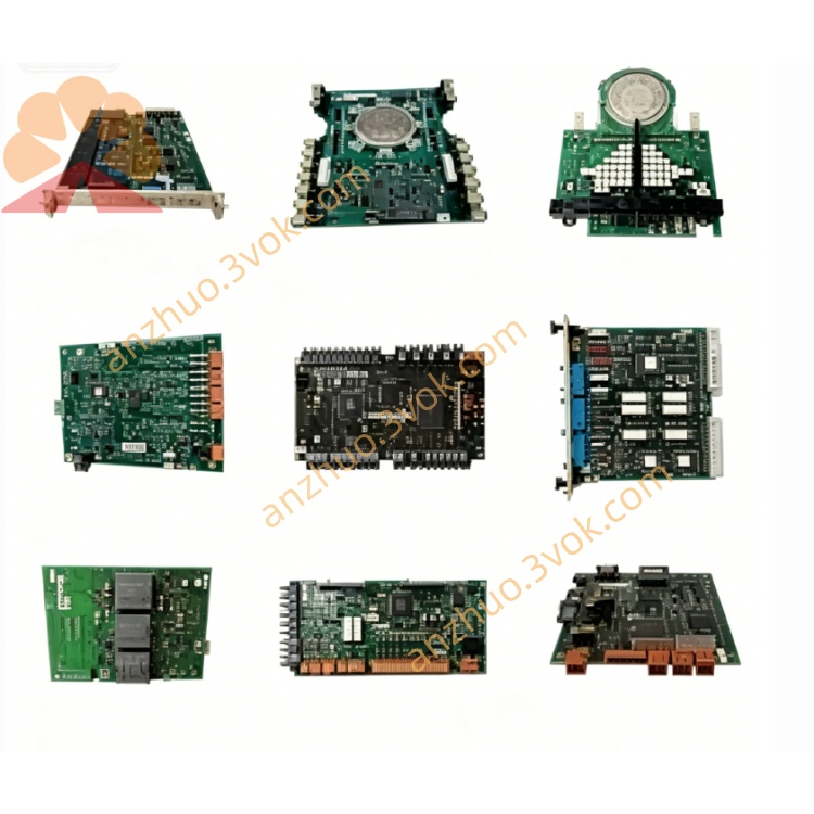
ABB 07DC92F The 8-channel relay output module of the AC31/Advant OCS (now known as Symphony Plus) system
ABB 07DC92F is an 8-channel relay output module belonging to the ABB AC31/Advant OCS (Symphony Plus) system. Different from the transistor-type I/O modules of 07DC92, 07DC92B and 07DC92E, this model adopts dry contact relay output design. It features high voltage isolation and strong load capacity, and can directly drive both AC and DC loads without additional intermediate relays.
Description
Product Introduction
ABB 07DC92F is an 8-channel relay output module belonging to the ABB AC31/Advant OCS (Symphony Plus) system. Different from the transistor-type I/O modules of 07DC92, 07DC92B and 07DC92E, this model adopts dry contact relay output design. It features high voltage isolation and strong load capacity, and can directly drive both AC and DC loads without additional intermediate relays.
Model Explanation
07 represents the I/O product line of ABB AC31/90 series. DC indicates the module is powered by 24 VDC system bus. 92 refers to the base I/O unit model. F stands for relay output type, which distinguishes it from transistor output versions such as B and E.
Technical Parameters
It is equipped with 8 SPDT dry contact relay channels. The rated load voltage is 250 VAC or 30 VDC. The rated resistive load current is 2 A per channel. The maximum switching power is 500 VA for AC loads and 60 W for DC loads. The isolation voltage between channels and the control system reaches 2500 VAC. The closing response time is less than 10 ms and the opening response time is less than 5 ms. The module is powered by 24 VDC from the system bus. The operating temperature ranges from 0 ℃ to +55 ℃. The protection class is IP20. It adopts standard 35 mm DIN rail mounting. The overall dimensions are 120 mm in width, 25.5 mm in height and 75 mm in depth, with a weight of approximately 0.45 kg. This product has obtained UL, CE and CCC certifications.
Interface and Communication Configuration
The terminal block consists of 24 VDC power terminals L+ and M, 8 relay terminals including common, normally open and normally closed contacts, as well as CS31 communication terminals. LED indicators are provided for running status, communication status, fault alarm and individual channel working status. The module connects to the main controller via CS31 bus to realize data transmission and command execution.
Core Functions
It supports direct drive of high voltage AC and DC loads with 250 VAC dry contacts, eliminating the need for intermediate relays. Complete electrical isolation of 2500 VAC effectively prevents on-site high voltage and interference from entering the control system and improves operation safety. The design is compatible with both AC and DC loads, suitable for various contactors, solenoid valves and indicator lamps. Adopting industrial-grade relays, the mechanical service life exceeds 10 million times, which adapts to frequent switching applications. It is capable of real-time channel status monitoring and fault alarming. It is recommended to install 2 A external fuses for overcurrent and short circuit protection.
Application Scenarios
It is widely applied in power plants to drive 220 VAC contactors, circuit breakers and alarm circuits. In chemical and metallurgical industries, it is used to control high-temperature valves, heaters and high-power solenoid valves. For water treatment projects, it can directly control 220 VAC water pumps, fans and electric valves. It is also an ideal choice for legacy system retrofitting, which helps save installation space and simplify wiring work.
Operation and Maintenance Instructions
Do not operate the contacts beyond the rated voltage and current range during wiring. Install a 2 A fuse for each relay channel. Keep the module away from strong electromagnetic interference during installation, and ground the shield layer of CS31 cable at one end only. Inspect the relay contacts regularly for ablation. Avoid long-term full-load operation and excessive frequent switching actions. When a fault occurs, check external fuses and loads first, then inspect the internal relays and communication circuits of the module.
Get a Quote