
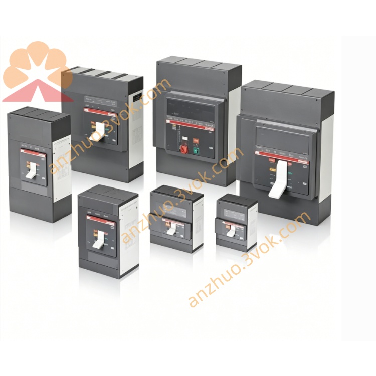
ABB 07DC91 Compact digital I/O module
ABB 07DC91 is a compact digital I/O module belonging to the ABB AC31/90 series PLC system. It is designed for digital signal acquisition and control output in industrial sites. Adopting reinforced housing and DIN rail mounting structure, the module features strong anti-interference performance, high operational stability and long service life. It can be connected with proximity switches, photoelectric sensors, push buttons, relays, solenoid valves and indicator lights, realizing reliable data interaction between the controller and on-site devices.
Description
Product Introduction
ABB 07DC91 is a compact digital I/O module belonging to the ABB AC31/90 series PLC system. It is designed for digital signal acquisition and control output in industrial sites. Adopting reinforced housing and DIN rail mounting structure, the module features strong anti-interference performance, high operational stability and long service life. It can be connected with proximity switches, photoelectric sensors, push buttons, relays, solenoid valves and indicator lights, realizing reliable data interaction between the controller and on-site devices.
Model Explanation
07 stands for the I/O module product line of ABB AC31/90 series. DC indicates the module adopts 24 VDC power supply and DC signal standard. 91 is the specific serial number of this model, which distinguishes modules with different channel quantities, functions and interface configurations in the same series.
Technical Parameters
The rated power supply voltage is 24 VDC with an allowable range from 12 VDC to 42 VDC. It is equipped with 16 digital input channels compatible with 24 VDC NPN and PNP signals, and 8 configurable digital output channels with rated load of 0.5 A per channel under 24 VDC. It serves as a slave station for CS31 bus and matches ABB AC31 series PLC. The operating temperature ranges from 0 ℃ to +55 ℃. The protection class is IP20. It adopts standard DIN rail installation. The overall dimension is approximately 25.5 mm in height, 75 mm in depth and 120 mm in width, and the weight is about 0.3 kg.
Interface and Communication Configuration
The front terminal block includes power terminals L+ and M, 16 digital input terminals DI1 to DI16, 8 digital output terminals DO1 to DO8 and CS31 communication terminals. It is equipped with CS31 bus interface to conduct high-speed cyclic data exchange with AC31 PLC master station. Multiple LED indicators are provided to display power status, CS31 communication status, channel operating status and fault information for convenient on-site diagnosis. Electrical isolation is applied between input, output circuits and the bus to enhance anti-interference capability.
Core Functions
This module supports real-time collection of switching signals from push buttons, limit switches, photoelectric switches and proximity switches via 16 input channels. The 8 output channels can directly drive actuators such as relays, solenoid valves, contactors and indicator lights. The output channels can be configured as normally open or normally closed through software to adapt to various control logics. It realizes real-time data uploading and control command distribution through CS31 bus connection with PLC. Built-in self-diagnosis function can detect over current, short circuit and communication anomalies, and trigger alarm through corresponding indicators.
Application Scenarios
It is widely applied in multiple industrial fields. In manufacturing industry, it is used for production line start-stop control, station detection, motor control and alarm indication. In process industry, it applies to pump and valve control, monitoring of liquid level and pressure switches as well as equipment interlock protection. It is also suitable for building automation including lighting, access control, fan and water pump control. Besides, it can be used in water treatment systems for dosing pump, solenoid valve and liquid level switch management, as well as in packaging and logistics industries for sensor detection, cylinder control and conveyor operation control.
Operation and Maintenance Instructions
Complete module installation on standard DIN rail only when the power is cut off, and ensure the buckle is firmly locked. Check terminal definitions carefully before wiring to prevent reverse connection of positive and negative power poles. Connect 24 VDC NPN or PNP sensors to digital input terminals, and connect loads with protective fuses to digital output terminals. Use shielded twisted pair cables for CS31 bus wiring and keep them away from high-voltage cables. After power on, confirm the power indicator stays on and the communication indicator flashes normally. Configure channel modes via PLC software and test input and output functions. Regularly remove dust from terminals and check the tightness of wiring connections. Avoid long-term operation in over temperature, humid and corrosive environments. In case of faults, cut off the power first to inspect external circuits. Replace the module if necessary and download configuration data again after replacement.
Get a Quote